
Led Light
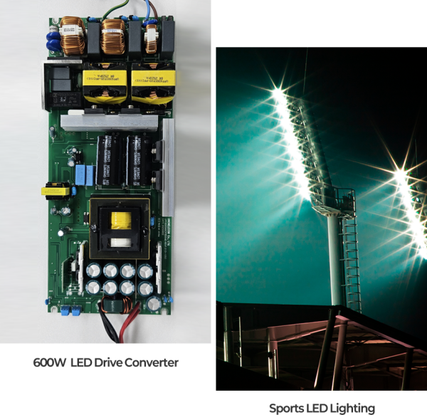
LED Converter
Device that Supplies Power to LED Lighting Equipment
Resonant converters for LED converters are devices that supply power to LED lighting equipment,
using resonant circuits such as LLC (Inductor-Inductor-Capacitor) resonant converters
to reduce switching losses
and provide high efficiency and long lifespan.
This resonant method plays an important role in enhancing the lifespan and reliability of LED lighting,
and is widely used in high-power LED lighting applications such as
street lights, tunnel lights, and sports lighting.
AP SEMI offers a diverse lineup of high-power MOSFET and RECTIFIER products
for these high-efficiency drives.
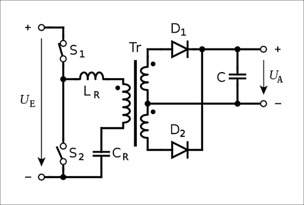
01
Resonant converter
basic_eng circuit diagram
02
Product
- High Voltage MOSFET
- High Power Rectifier
- Schottky Barrier Diode
- Bridge diode
- Optocoupler
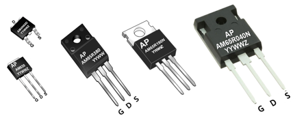
03
High Power Transistor
High Power TR
In LED converters (SMPS), power MOSFETs are used as power TRs
that convert input voltage to desired DC voltage and play a switching role
in supplying stable current and voltage to LEDs.
Since MOSFET characteristics significantly affect converter efficiency
and noise reduction performance, MOSFET characteristics must be
fully considered when designing LED lighting.
MOSFET Application 01
High-Efficiency Power Control
Since converter efficiency varies depending on MOSFET characteristics (e.g., on-resistance, switching speed),
select MOSFETs with high efficiency.
MOSFET Application 02
Heat Generation
LED converters with high current generate heat, so consider appropriate heat dissipation measures
and select MOSFETs with low heat generation and good durability. Since heat dissipation capability
varies greatly depending on package type, check PD (Power Dissipation) before selection.
MOSFET Application 03
Voltage and Current
Select MOSFETs with sufficient specifications to handle
the input voltage and output current required for LED converters.
04
Main MOSFET Application Devices

SMPS
TV, Adaptor, Charger
- C 600V~700V
- CF 600V~700V
Lighting
Led lighting
- C 650V - 800V
- CF 650V - 800V

Automotive
Charging station
- D 600V~650V
- DF 600V~650V
05
MOSFET Types and Characteristics
-
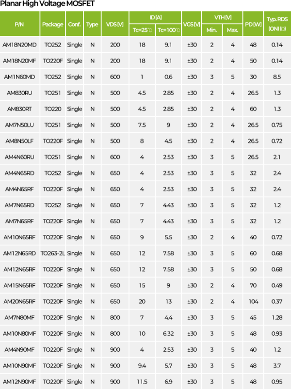
01
Planar MOSFET
• Advantages
Simple structure, easy to manufacture with low cost, and has low noise characteristics
for good EMI performance.• Disadvantages
Large device ON resistance (RDS(on)), slow switching speed, increased device size
at the same voltage rating, and lower efficiency. -
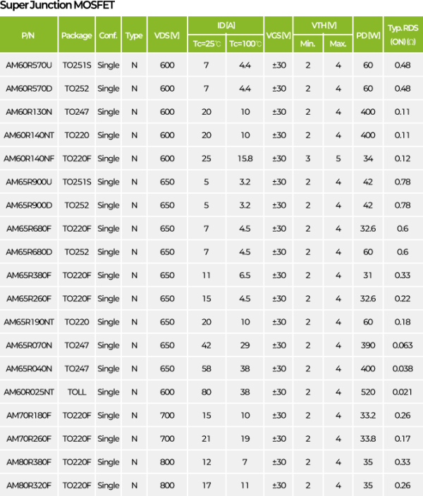
02
Super Junction MOSFET
• Advantages
ON resistance (RDS(on)) and gate charge (Qg) are significantly lower than Planar MOSFETs, improving efficiency with high-speed switching performance.
• Disadvantages
Larger PN Junction area than Planar type results in higher reverse recovery current (irr)
during ON-OFF transitions, tends to have higher noise during high-speed switching, and is
more expensive due to highly integrated structure implementation. -
03
SiC MOSFET (Silicon Carbide)
• Advantages
Has wider bandgap than Si, delivering excellent performance even at high temperatures and voltages,
providing high efficiency with low conduction loss and high switching speed. Particularly suitable
for power conversion devices such as electric vehicle inverters and OBC (onboard chargers).• Disadvantages
Requires high-temperature processes above 2000℃, which is time-consuming and significantly
increases costs. High price and reliability issues (SiO2-SiC interface problems) result in low yields,
which can be a supply issue during commercialization. -
04
GaN MOSFET (Gallium Nitride)
• Advantages
Higher electron mobility than SiC enables very fast switching speeds, low conduction resistance
minimizes power loss and increases power density, reducing size and weight of compact power
supply devices while improving efficiency.• Disadvantages
Higher conductivity than SiC can limit possible power density, and yield and reliability
issues still exist.
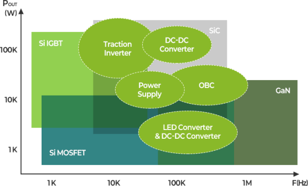
06
Power Transistor by Application
Power Transistor by Application
Silicon MOSFETs (Planar MOSFET, Super Junction MOSFET) are
the most suitable technology for general consumer and industrial devices,
while SiC MOSFET is the most suitable technology for automotive power.
However, even in automotive applications, the Heating Block
primarily adopts silicon IGBT.
MOSFET Lineup
07
Rectifier DiodeRectifier Diode
Since the forward voltage of rectifier diodes in power converters is directly related to power loss,
high-efficiency power diodes must be used to increase efficiency.
By using diodes with short reverse recovery time
(TRR: Reverse Recovery Time)
to reduce switching losses, efficiency is increased and losses are minimized.
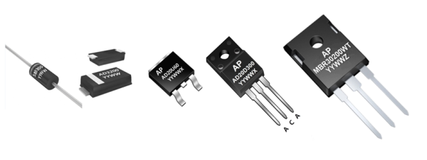
Standard Rectifier
Rectifier Diode with slow reverse recovery characteristics with TRR of 2-20 micro Sec.,
mainly used in primary rectification of adapters or power supplies or low-frequency circuits such as toys
Fast Recovery Rectifier
Rectifier Diode with TRR of 100~750 nano Sec., used in high-frequency (20~50Khz) circuits
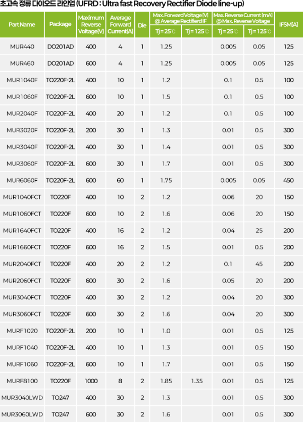
Ultra Fast Recovery Rectifier
Rectifier Diode with TRR of 35~75 nano Sec., generates less heat than Fast Recovery Rectifier,
mainly used in high-voltage (400V~1000V), high-frequency (50Khz or higher) circuits
Ultra High Efficient Rectifier
High-speed rectifier Diode with TRR of 10~35 nano Sec., low resistance ($V_F$) reduces heat generation.
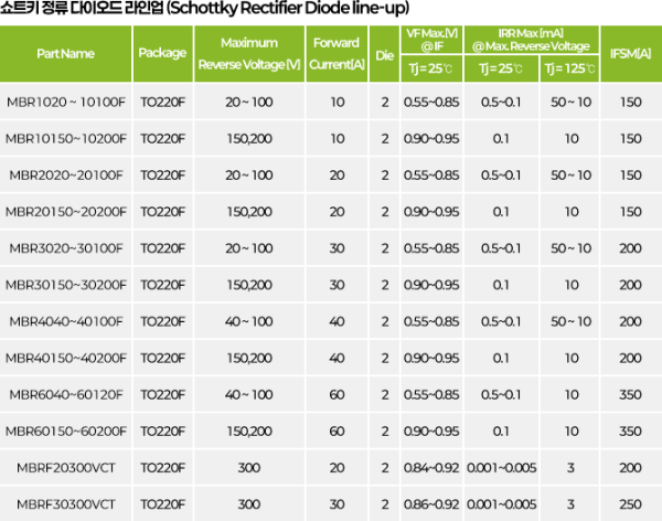
Used in low-voltage (up to 200~600V), high-frequency (50~200Khz) circuits
Schottky Barrier Rectifier
Very low internal resistance and fast operation speed, but low operating voltage and high leakage current.
Mainly used in high-frequency, high-current, low-voltage rectification
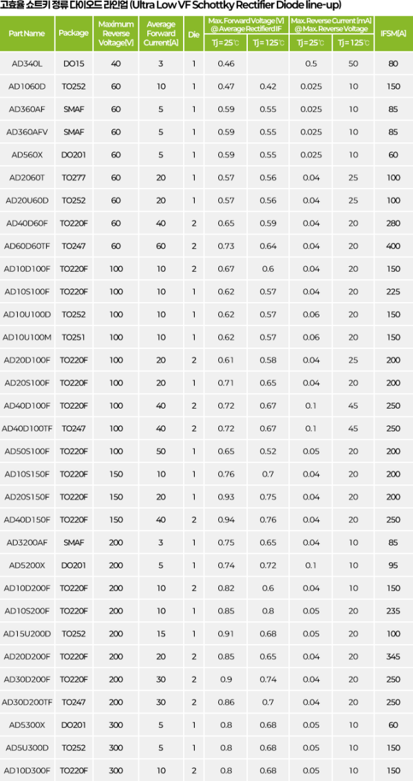
Ultra Low $V_F$ Schottky Rectifier
Schottky rectifier that uses trench process compared to general Schottky to significantly reduce forward voltage
08
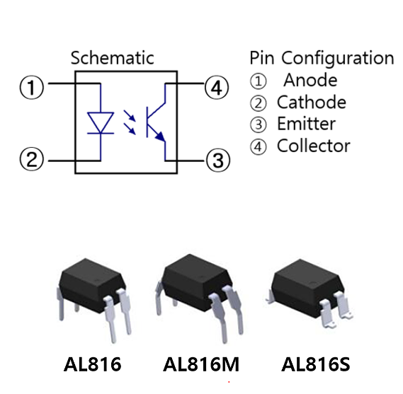
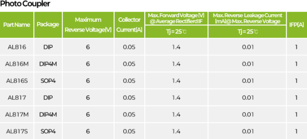
Photocoupler
Photo Coupler, Optocoupler, Isolator
A photocoupler is a device that transmits signals between the input and output circuits
in an electrically isolated state by activating the phototransistor (light-receiving section)
with light emitted when the internal LED turns on. When the electrical signal of the input circuit
flows current to the LED to generate light, this light passes through the phototransistor
to flow current to the output circuit, and through this,
signal transmission between the two circuits is achieved.
09
Shunt Regulator
Shunt Regulator
A shunt regulator is a device that regulates voltage to maintain stable output
despite input voltage fluctuations or load changes.
'Shunt' refers to a method of regulating voltage by connecting in parallel
to the load that conducts current, operating on the same principle as a shunt
to supply stabilized power at a specific voltage level.

-
이전글
-
다음글다음글이 없습니다.